Table of Contents
Getting Started
A simple tutorial that explains the basic setup and command needed to start using the QuimDC.
Requirement :
- QuimDC
- USB/Serial port cable
- DC laboratory power supply
- DC motor
- Two Jumpers
Connection
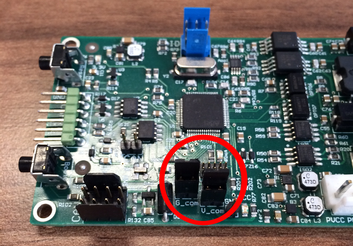
The QuimDC is divided into two parts, the logical one and the power one. In this tutorial we will power the two parts with one laboratory power supply. We need to put two jumper on G_com and V_com like in the picture below.
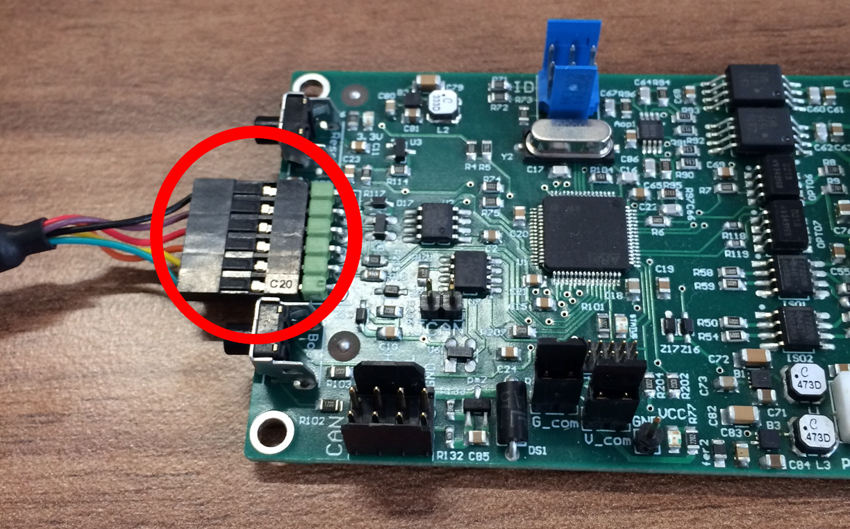
We connect the serial port.
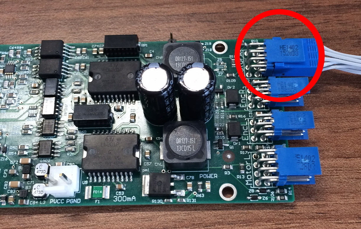
We connect the motor to the Motor R blue connector.
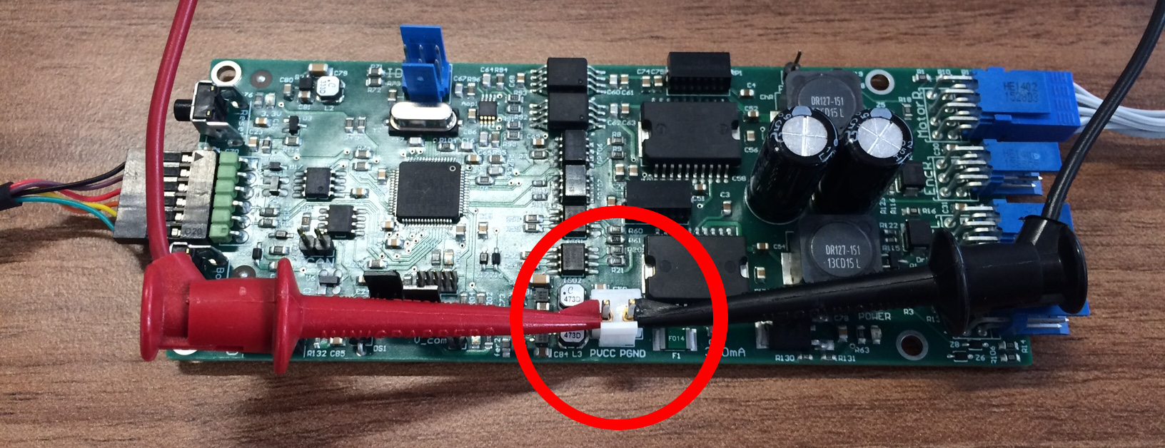
Then we will power the QuimDC with a tension between 12 V to 48 V.
Command Line Interface
In order to communicate with the board, we need a terminal connected to the QuimDC serial port (115200bps, 8 data bits, 1 stop bit, no parity). Once your terminal is open, type “print_board_states” command.
>print_board_states

>D:001-000000
D:002-000000 ####################
D:003-000000 # THE BOARD STATES #
D:004-000000 ####################
D:005-000000 Operational Mode : no
D:006-000000 Motor Watchdog value : -1
D:007-000000 Right Motor(1) :
D:008-000000     Control : Pwm Open Loop
D:009-000000 Left Motor(2) :
D:010-000000     Control : Pwm Open Loop
The following line …
D:005-000000 Operational Mode : no
… tells us that we are not in operational mode, the motor is disabled for now.
Enter “enter_operational_mode” and use the up arrow to retrieve the “print_board_states” command and press enter.
>enter_operational_mode

>print_board_states

>D:011-000000
D:012-000000 ####################
D:013-000000 # THE BOARD STATES #
D:014-000000 ####################
D:015-000000 Operational Mode : yes
D:016-000000 Motor Watchdog value : -1
D:017-000000 Right Motor(1) :
D:018-000000     Control : Pwm Open Loop
D:019-000000 Left Motor(2) :
D:020-000000     Control : Pwm Open Loop
There is now 'yes' beside Operational Mode, the board is in operational mode, the motor are enabled. Take care that the motor watchdog value as a negative value to deactivate it. If the value is positive, any reference signal will be set to 0 after the watchdog duration ( in ms ) if no signal is received. To set the watchdog value, use the function “motor_watch_dog_value”.
In this case, the motors are controlled in open loop with the pwm. ( If it is not the case, the control can be changed with loop_function <motor> <loop_type>, for more information about the control_loops see control_loops) With 128 pwm, the motors are stopped and don't move. Use the ref_pwm command to set a new PWM and make the motor move.
>ref_pwm 1 40
The PWM send to the right motor (1 for the right one, 2 for the left one) is now 128 + 40. To stop the motor use :
>ref_pwm 1 0
The PWM value is somewhere between 0 and 255, with 128 for motor stop.


